- Coats 6401 Truck Tire Balancer
- Coats Tire Balancer Troubleshooting
- Coats 6401 Tire Balancer
- Coats 6401 Tire Balancer Manual
- Coats 6401 Wheel Balancer
- COATS 6401 Truck Wheel Balancer. 17. Preventative Maintenance. The balancer requires only minor maintenance to. Keep the unit operating properly. NEVER use compressed air or a water hose to clean any part of your balancer. Keep the display clean and clear. Use a vaporizing. Cleaner only.
- Coats 6401 Pdf User Manuals. View online or download Coats 6401 Installation And Operating Instructions Manual. Coats Manuals; Tools; 6401; Coats 6401 Manuals Manuals and User Guides for Coats 6401. We have 1 Coats 6401 manual available for free PDF download: Installation And Operating Instructions Manual. Computer Truck Wheel Balancer.
- Get COATS 6401 Computer Truck Wheel Balancer User Manual. Get all COATS manuals! Sign up to create an account Facebook Twitter. By clicking Create Account, you agree to the Company’s. Don't see a manual you are looking for? Tell us what's missing. Who We Are About Us Company Careers.
- COATS 6401 Truck Wheel Balancer. v Owner’s Responsibility To maintain machine and user safety, the responsi-bility of the owner is to read and follow these instruc-tions:. Follow all installation instructions. Make sure installation conforms to all applicable Local, State, and Federal Codes, Rules,.
- Hennessy Drive, LaVergne, TN USA 615/641-7533 800/688-6359 Manual Part No.: 8144112 13 HENNESSY INDUSTRIES INC. Manufacturer of AMMCO ®, COATS and BADA Automotive Service Equipment and Tools. Revision: Computer Truck Wheel Balancer ® Parts Identification READ these instructions before placing unit in.
View and Download Coats 775 installation operation & maintenance online. 775 Wheel Balancers pdf manual download. Also for: 875. Wheel Balancers Coats XR 1750 Installation Instructions Manual. Xr 1750 series (40 pages). Page 5 Owner’s Responsibility Definitions of Hazard Levels To maintain machine and user safety.
Connect to Power
Your factory trained COATS
®
Service Technician should do the
final check to verify the power installation before connecting the
balancer to a power supply. Failure due to improper power con-
nection will void the warranty.
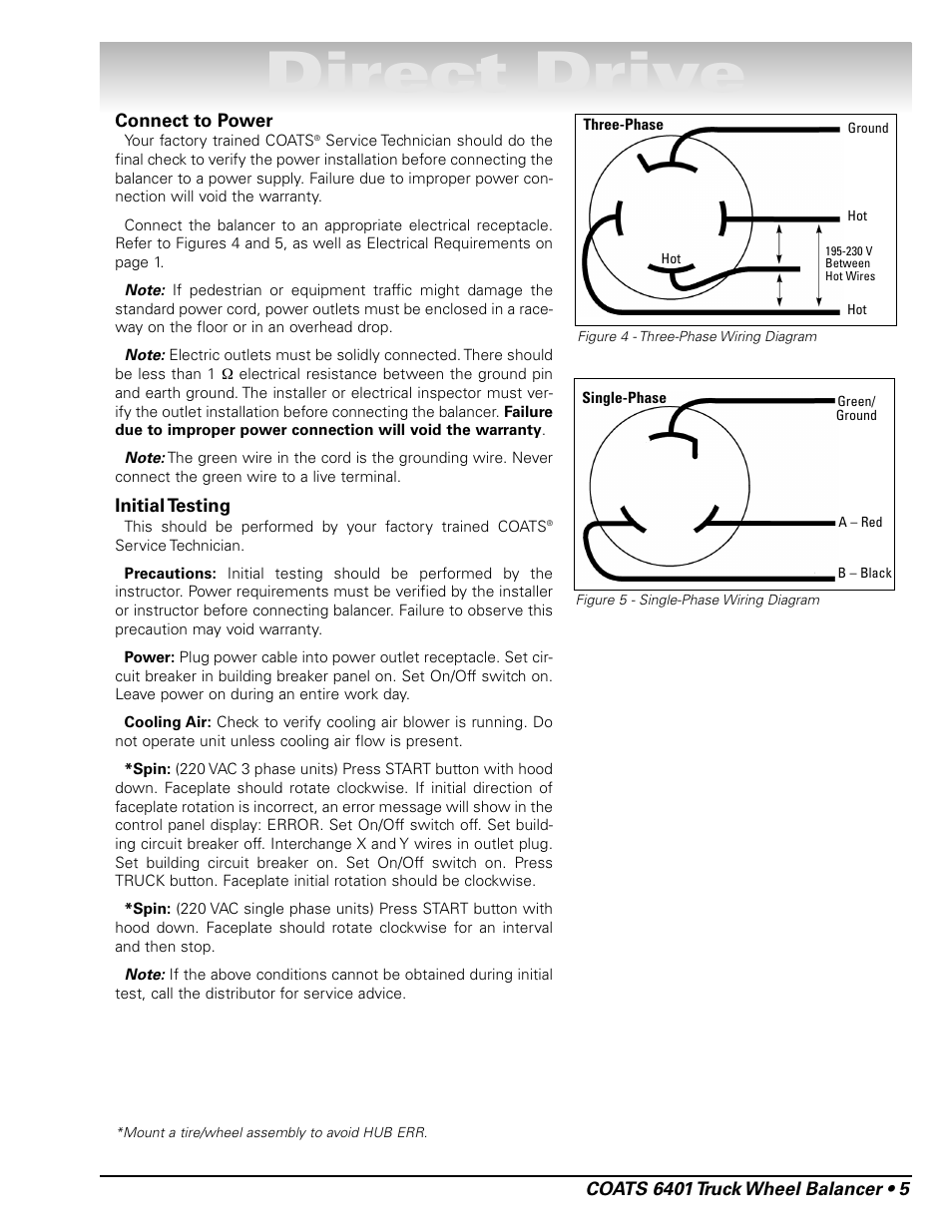
Connect the balancer to an appropriate electrical receptacle.
Refer to Figures 4 and 5, as well as Electrical Requirements on
page 1.
Note: If pedestrian or equipment traffic might damage the
standard power cord, power outlets must be enclosed in a race-
way on the floor or in an overhead drop.
Note: Electric outlets must be solidly connected. There should
be less than 1 Ω electrical resistance between the ground pin
and earth ground. The installer or electrical inspector must ver-
ify the outlet installation before connecting the balancer. Failure
due to improper power connection will void the warranty.

Note: The green wire in the cord is the grounding wire. Never
connect the green wire to a live terminal.
Initial Testing
This should be performed by your factory trained COATS
®
Service Technician.
Precautions: Initial testing should be performed by the
instructor. Power requirements must be verified by the installer
or instructor before connecting balancer. Failure to observe this
precaution may void warranty.
Power: Plug power cable into power outlet receptacle. Set cir-
cuit breaker in building breaker panel on. Set On/Off switch on.
Leave power on during an entire work day.
Cooling Air: Check to verify cooling air blower is running. Do
not operate unit unless cooling air flow is present.
*Spin: (220 VAC 3 phase units) Press START button with hood
down. Faceplate should rotate clockwise. If initial direction of
faceplate rotation is incorrect, an error message will show in the
control panel display: ERROR. Set On/Off switch off. Set build-
ing circuit breaker off. Interchange X and Y wires in outlet plug.
Set building circuit breaker on. Set On/Off switch on. Press
TRUCK button. Faceplate initial rotation should be clockwise.
*Spin: (220 VAC single phase units) Press START button with
hood down. Faceplate should rotate clockwise for an interval
and then stop.
Note: If the above conditions cannot be obtained during initial
test, call the distributor for service advice.
*Mount a tire/wheel assembly to avoid HUB ERR.
Direct Drive
Coats 6401 Truck Tire Balancer
COATS 6401 Truck Wheel Balancer • 5
Figure 4 - Three-Phase Wiring Diagram
Figure 5 - Single-Phase Wiring Diagram
Three-Phase
Ground
Hot
195-230 V
Between
Hot Wires
Hot
Hot
Single-Phase
Coats Tire Balancer Troubleshooting
A – Red
B – Black
Coats 6401 Tire Balancer
Green/
Ground